
Cooling of Cemented Carbide and p/M tool steel Rolls
During the hot rolling process, only a very small area of the roll pass groove surface is directly in contact with the hot bar or rod. Different points on the groove surface go through a heating and cooling cycle. See Figure 1 for the temperature profile at any point during one revolution of the roll.
Lorem ipsum dolor sit amet conse ctetur adipisicing elit, sed do eiu.
Environmental
Amet conse ctetur adipisicing elit, sed do eiusmod tempor incid.
Why is Roll Cooling Important?
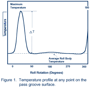
If the roll is not cooled during the rolling process, or if the cooling is not efficient, the maximum roll temperature, the average roll body temperature and the temperature difference (DT) can steadily increase with time. In addition, temperature gradients can develop within the roll.
The alternate expansion and contraction caused by the heating and cooling cycle, coupled with the temperature gradients, can cause large stresses to build up in the surface layer in the pass groove. Such stresses can lead to the formation of a network of thermal cracks, often referred to as “heat-check” or “fire” cracks.
Because cemented carbides and P/M tool steels are ultrahard materials, they are particularly sensitive to thermal cracking. Therefore, efficient cooling of the rolls is critical to obtaining optimum performance levels from such rolls.
Considerations for Designing Suitable Roll Cooling Systems
Cooling of cemented carbide and tool steel rolls can be easily and conveniently performed by spraying the pass groove surface with a stream of high pressure water. The volume and pressure of water, as well as the direction of the water stream(s), will depend upon a variety of process parameters which includes, but is not limited to, size and shape of pass, temperature of material being rolled, rolling speed, area reduction, mass of roll, thermal conductivity and thermal cracking resistance of the roll material.
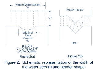
Based on experience, SinterMet recommends the following guidelines be used during the design of cooling systems. The temperature of the cooling water should not exceed the ambient temperature by more than 10°F (6°C). Pass groove surface temperature should not exceed cooling water temperature by more than 25°F (14°C). Width of water stream is typically twice the width of the pass groove (as shown in Figure 2(a)). Whenever possible the spray pattern should be designed to match the profile of the pass (as shown in Figure 2(b)).
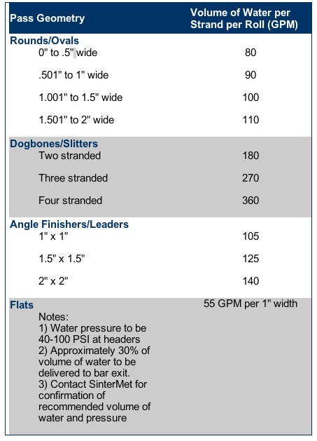
Recommended Requirements for Volume and Pressure of Water
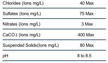
Recommended Water Chemistry
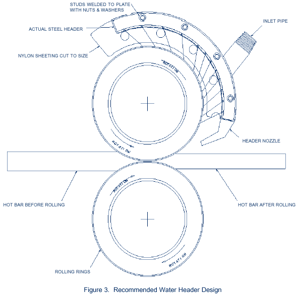
Recommended Water Header Design
SinterMet has developed a new and improved design for water headers (shown in Figure 3). The design incorporates the following advanced features:
- A separate high pressure nozzle which directs approximately 30% of water volume at the bar exit.
- Side shields made of plexiglass (or other suitable material) to help concentrate the flow of water on to the pass groove surface.
- Slots, ports or jets cut in the header which help to direct a stream of water at an angle on to the groove surface. This helps the water to cascade down the groove surface and hence to increase the contact time (i.e., heat transferred) between the water and the roll.
- The header design shown in Figure 3 (below) helps to greatly improve cooling efficiency. Note the angular overage from bar exit for slightly more than 90°.
 Address
 FAX
FAX FACEBOOK